January 09, 2018 / by Sergey Kapustin
Custom Protocol For Serial Link Communication
For my current project, after considering a couple of options, I chose to develop a custom communication protocol to connect two programs: one runs on Arduino and another on a Raspberry Pi (RPi). In this post, I’d like to share my experience of going through the development process.
On YouTube
Requirements
My project’s requirements are:
- Make the communication over a serial link more resilient to errors
- Use a messaging protocol that requires less resources to handle
- Write portable code to share between Arduino and RPi
Communication Link Errors
The Arduino and RPi are connected via a serial cable. The data on a serial link is streamed. By default, the link doesn’t provide packet framing such that either side of the communication doesn’t know where a message begins or ends. This creates a problem when a program tries to interpret a message which is not received completely or whose bytes are dropped for some reason.
To help the program distinguish one message from another, a stream of data should include some message delimiter. In other words, frame the chunks of bytes into packets.
If my program transmitted human-readable messages, for example in ASCII, I may use a newline character as a delimiter. But ASCII-encoded data uses up more bandwidth to move across the wire than binary-encoded data.
For example, to send a number “12345” and delimit it with a newline character “\n”, the message-transmission hardware would need to send six bytes, one byte per character.
Here is a human-readable message:
1
2
$ cat message.txt
12345
This is what the hardware transmits across the wire:
1
2
3
$ hexdump -C message.txt
00000000  31 32 33 34 35 0a                                 |12345.|
00000006
If the program used binary encoding instead, the hardware would only need to transmit three bytes: two bytes to represent the number (if using a 16-bit integer), plus one byte to represent the newline.
For example, write the number 12345 and a newline character as raw bytes to a file:
1
2
3
4
d = int(12345).to_bytes(2, byteorder='big')
d += ord('\n').to_bytes(1, byteorder='big')
f = open("message.binary", 'wb')
f.write(d)
Read the file content in hex:
1
2
3
$ hexdump -C message.binary
00000000  30 39 0a                                          |09.|
00000003
It would take half the time and bandwidth to send a binary-encoded message than to send a human-readable, ASCII-encoded text.
Since the data is not meant for my consumption but for the computer’s, I choose more efficient binary encoding. True, it makes debugging the protocol slightly more difficult, but still doable.
There is one problem with using some random character like the newline with binary data but without additional provision. The reason is that every ASCII character is represented by a numeric value as any other data unit. For example, a newline is represented by number 10. If my program sends some sensor’s value 10 and a newline as a delimiter, which one should the receiving program treat as an indicator of the message end? What the message had 20 such values in a single message?
To address this, I have to use a different approach to delimit the packets. One efficient and simple protocol to achieve this is COBS.
Framing Protocol
In short, with COBS protocol, packets are delimited with a zero byte (EOP - end of packet). In order to not confuse EOP with other data, the algorithm would replace every zero byte in a message with an offset (1-255) that points to a next zero byte. Every packet is prepended with one overhead byte (OHB) that contains the very first offset. If a message doesn’t contain any zero bytes, then OHB points to EOP.
Now the receiving program won’t get confused about where a message ends because a zero byte has only one meaning - to represent the end of a packet.
From the Wiki:
1
2
3
4
5
6
7
8
| Example | Unencoded data (hex) | Encoded with COBS (hex) |
| ------- | -------------------- | ----------------------- |
| 1       | 00                   | 01 01 00                |
| 2       | 00 00                | 01 01 01 00             |
| 3       | 11 22 00 33          | 03 11 22 02 33 00       |
| 4       | 11 22 33 44          | 05 11 22 33 44 00       |
| 5       | 11 00 00 00          | 02 11 01 01 01 00       |
| 6       | 01 02 ... FE         | FF 01 02 ... FE 00      |
Break-down of example #3
1
2
3
4
5
6
7
8
9
10
[OHB]                                : Overhead byte (Start of frame)
  3+ -------------->|                : Points to relative location of first zero symbol
                    2+-------->|     : Is a zero data byte, pointing to next zero symbol
                              [EOP] : Location of end-of-packet zero symbol.
  0     1     2     3     4    5     : Byte Position
  03    11    22    02    33   00    : COBS Data Frame
        11    22    00    33         : Extracted Data

OHB = Overhead Byte (Points to next zero symbol)
EOP = End Of Packet
The protocol can be used as is, but I want to modify it slightly for my conceived situation.
One issue I have is that EOP sits at the end of a packet. This may become a problem when the program which attempt to process incoming messages starts reading the serial stream for the first time or after a failure. When the program detects EOP byte, it has no easy way of back-tracking the bytes of a packet that came before EOP to verify that the they represent a complete message. Given that reasoning, I moved a packet delimiter to the front so that it represents a Start Of a Packet - SOP.
Since there is no more EOP, the last offset within a packet has nowhere to point to, but it cannot have a value 0. Thus, the further modification is to reserve some value to indicate that condition. I chose the value 255.
After making the adjustments, example #3 now would look like this:
1
2
3
4
5
6
7
8
9
10
[SOP]                              : Location of start-of-message zero symbol
     [OHB]                         : Overhead byte (Start of frame)
      3+ -------------->|          : Points to relative location of first zero symbol
                       255         : Last zero data byte. Stop decoding
0     1     2     3     4     5    : Byte Position
00    03    11    22    FF    33   : Data Frame
            11    22    00    33   : Extracted Data

SOP = Start Of Packet
OHB = Overhead Byte (Points to next zero symbol)
Application Protocol
Once the program extracts a packet using the above framing protocol, it needs to know what type of message is contained within the packet. Here comes in an application-level protocol. Let’s call it clawbot protocol.
The fields and their size in bytes are as follows:
1
2
3
| PID | Tag | Data |
| --- | --- | ---- |
| 1   | 1   | N    |
- PID - packet identifier. The ID is incremented for every packet that is being sent out. The value is used for message tracking. Size: 1 byte. Value minimum: 1, maximum: 255
- Tag - message type. Size: 1 byte. Value minimum: 1, maximum: 255
- Data - message content. Variable-length content according to message type. Size minimum: 0, maximum: 252.
So far, my project uses just a few types of messages for communication between Arduino and RPi. I’ll describe two examples:
1
2
3
4
| Tag | Data (hex)                                      |
| --- | ----------------------------------------------- |
| 02  | 01                                              |
| 03  | 01 01 01 01 02 28 04 61 03 96 01 01 01 01 01 FF |
- Tag 02: Message “get state”. RPi sends this message to Arduino to request state update. When data field contains value 00, RPi asks only for one state update. When the field is 01, RPi asks to send continuous updates at a pre-defined interval (e.g. 50mS)
- Tag 03: Message “state update”. Arduino sends this message to update RPi with the state. The update contains eight, two-byte binary-encoded values such as sensor readings, clicks from wheel encoders, and others
Here is an example of a complete packet that Arduino may receive from RPi:
1
2
3
| SOP | OHB | PID | Tag | Data |
| --- | --- | --- | --- | ---- |
| 00  | FF  | 01  | 02  | 01   |
The steps that Arduino goes through when checking for new messages are as follows:
- Append the available number of bytes from serial stream to internal buffer
- Locate SOP by checking one byte at a time. Drop non-SOP bytes to synchronize with the stream
- If SOP is located, read OHB
- If OHB is available, skip past PID to Tag. (PID is used for debugging at this time)
- If Tag is available, validate the message type, and determine how many more bytes are required for the message to be complete. In case of Tag 02, the protocol requires one more byte
- If all required bytes are available, decode packet data using (modified) COBS codec
- If message type is “get state”, send the first state update and set internal flag to indicate if continuous updates were requested
- Reset the buffer to the next available byte. Go to step 2, and repeat the process
If at any step, there is insufficient number of available bytes, the message-processing phase terminates. Arduino repeats the steps above at the next message check, which is configured to trigger every 50mS.
The steps that RPi performs while expecting state updates are similar. Of course, the message type and the number of bytes expected are different.
Testing and Debugging
Most of the code for encoding and decoding messages is shared between Arduino and RPi. This simplifies testing and debugging because that work can be performed on a desktop computer. The only difference is in interfacing with a serial hardware device.
To read and write binary messages with Arduino, the firmware uses standard Serial::readBytes and Serial::write. The program on RPi uses serial link parameters from termios.h and system calls to interact with the hardware. The link parameters, if not used with care, can induce minor headache. One such occasion is described next, along with the steps it took to debug the problem.
On RPi, during runtime I would get occasional errors coming from the codecs. The error-handling described above did its job: malformed packets were dropped, the processing comes back to normal shortly after.
For example, in the log below, line 2 indicates an error. Subsequent lines indicate that processing has recovered, and the program received a valid state message:
1
2
3
4
5
2018-01-09T13:59:42,620 DEBUG 0x7f60cb7fe700: Check messages
2018-01-09T13:59:42,570 ERROR 0x7f60caffd700: Decode error: 2048
2018-01-09T13:59:42,620 DEBUG 0x7f60cb7fe700: Check messages
2018-01-09T13:59:42,620 DEBUG 0x7f60cb7fe700: Buff available: 20, remaining: 39, size: 59, hex: 00:03:0E:03:01:01:01:01:02:11:04:61:03:20:01:01:01:01:01:FF
2018-01-09T13:59:42,620 DEBUG 0x7f60cb7fe700: State: 0,0,17,97,800,0,0,0
After adding a unit test that would continuously read state messages from Arduino, and analysing the output, a reproducible pattern has emerged. All packets are expected to be 20-byte long. The malformed packet has only 19 bytes. The received data is missing one byte, and it looks like that byte is a packet ID.
In the log below, on line 3, hex string representing raw packet data has value 03 at position 3. Instead, the value is supposed to be 0D, because it is the next packet after 0C. The unit test error reports that a received message type (fourth field, value 01) is not what is expected (value 03):
1
2
3
4
5
6
7
Episode: 12, io: 20, buff: 20, remaining: 0, size: 20, hex: 00:03:0C:03:01:01:01:01:02:2A:02:61:01:01:01:01:01:01:01:FF
State: 0,0,42,97,0,0,0,0
Episode: 13, io: 19, buff: 19, remaining: 1, size: 20, hex: 00:03:03:01:01:01:01:02:2B:02:62:01:01:01:01:01:01:01:FF
Expected equality of these values:
  3
    msg_type
        Which is: '\x1' (1)
But where does PID field disappear? It could be on Arduino, or in wires during transport, or somewhere on RPi.
To test if the program on Arduino (Mega2560) sends proper messages, I set up an additional serial interface to duplicate state messages:
1
2
3
4
5
6
ClawbotCodec::encodeState(&wbuff_, uvals, svals);
world_comm_->write(wbuff_.read_ptr(), wbuff_.available());

if (debug_comm_ != nullptr) {
  debug_comm_->write(wbuff_.read_ptr(), wbuff_.available());
}
That interface was hooked up to a terminal program “screen” running on RPi. The Screen would simply output the data it receives to a file:
1
screen -L /dev/ttyUSB0 115200
Upon inspection, all packets that arrived from the debug serial interface were well-formed.
To check if the messages are transmitted to RPi without damage, I hooked up an oscilloscope to the “malfunctioning” serial line and verified that the data was in fact delivered to RPi without problems. Note, the “missing” byte 0D at the third position from the left:
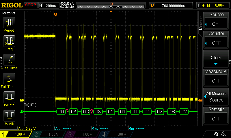
Every time the test was re-run, the same message had a problem - #13 (0D in hex). The ASCII table indicates that value 13 is a carriage return character (‘\r’). On Windows, this character is part of a sequence that represents a newline:
1
\r\n
Since my program deals with raw bytes, why would a text-related character play a role? This led me to check serial link parameters that are set up with termios.
Lo and behold, after playing with text-mode for the link, my code had this left over:
1
options.c_iflag = IGNPAR | IGNCR;
That instructs serial I/O driver to ignore carriage returns (IGNCR). Of course! The serial driver as instructed would ignore every byte that has value 13 (0D in hex).
After enabling the raw mode, which tells the I/O to just pass all bytes to the reading program:
1
cfmakeraw(&options);
the decoding errors were gone:
1
2
3
4
5
6
7
8
9
10
11
12
13
14
15
16
17
18
2018-01-09T13:59:42,420 DEBUG 0x7f60cb7fe700: State: 0,0,40,98,800,0,0,0
2018-01-09T13:59:42,470 DEBUG 0x7f60caffd700: State: 0,0,14,98,800,0,0,0
2018-01-09T13:59:42,620 DEBUG 0x7f60cb7fe700: State: 0,0,17,97,800,0,0,0
2018-01-09T13:59:42,670 DEBUG 0x7f60caffd700: State: 0,0,43,98,800,0,0,0
2018-01-09T13:59:42,720 DEBUG 0x7f60caffd700: State: 0,0,41,110,800,0,0,0
2018-01-09T13:59:42,770 DEBUG 0x7f60cb7fe700: State: 0,0,42,97,800,0,0,0
2018-01-09T13:59:42,820 DEBUG 0x7f60cb7fe700: State: 0,0,42,97,800,0,0,0
2018-01-09T13:59:42,870 DEBUG 0x7f60cb7fe700: State: 0,0,43,98,800,0,0,0
2018-01-09T13:59:42,919 DEBUG 0x7f60cb7fe700: State: 0,0,41,111,800,0,0,0
2018-01-09T13:59:42,969 DEBUG 0x7f60cb7fe700: State: 0,0,41,97,800,0,0,0
2018-01-09T13:59:43,019 DEBUG 0x7f60cb7fe700: State: 0,0,41,97,800,0,0,0
2018-01-09T13:59:43,069 DEBUG 0x7f60cb7fe700: State: 0,0,42,97,800,0,0,0
2018-01-09T13:59:43,119 DEBUG 0x7f60cb7fe700: State: 0,0,41,99,800,0,0,0
2018-01-09T13:59:43,170 DEBUG 0x7f60cb7fe700: State: 0,0,16,97,800,0,0,0
2018-01-09T13:59:43,219 DEBUG 0x7f60cb7fe700: State: 0,0,33,97,800,0,0,0
2018-01-09T13:59:43,269 DEBUG 0x7f60cb7fe700: State: 0,0,42,97,800,0,0,0
2018-01-09T13:59:43,319 DEBUG 0x7f60cb7fe700: State: 0,0,19,98,800,0,0,0
...