December 06, 2017 / by Sergey Kapustin
Ir Noise Capacitor And Power
After connecting an infrared sensor to my Arduino, I noticed that an ultrasonic sensor, which is connected to the same board, started reporting inconsistent measurements. The investigation took me a few hours, but now I know better to pay attention to the power requirements for electronic components.
In this post, I’ll share the steps I took to resolve the issue.
On YouTube
Analysis
When only the ultrasonic sensor is connected, the measurements it reports are fairly stable and the power line trace looks clean.
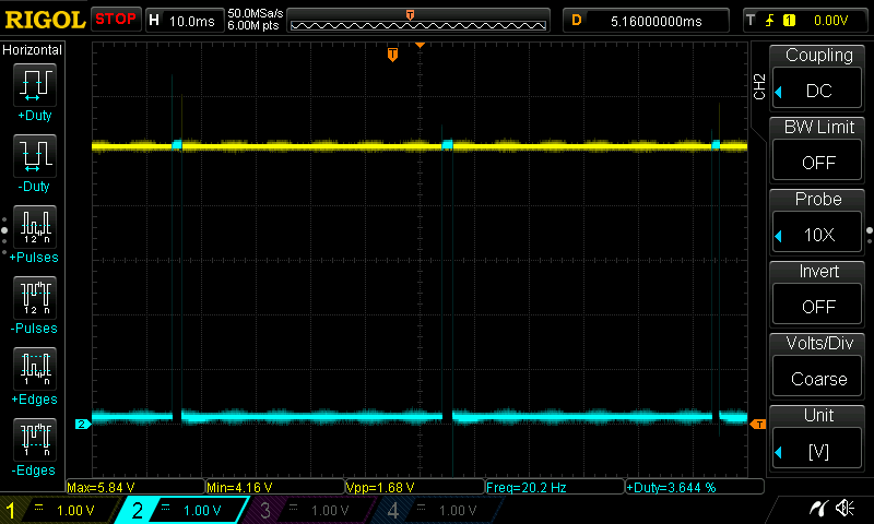
Good measurements:
1
2
3
4
5
data: 22
---
data: 22
---
data: 22
Once IR sensor is connected, the ultrasonic sensor starts reporting inconsistent values. The 5-volt VCC from Arduino shows very noisy pattern:
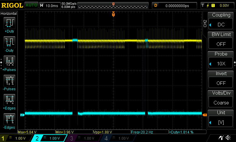
Bad measurements:
1
2
3
4
5
6
7
8
# The data is output every second without physically moving
# ultrasonic sensor or an object in front:

data: 12
---
data: 43
---
data: 86
After connecting a 12-volt battery to the barrel connector, the noise seems to decrease just slightly:
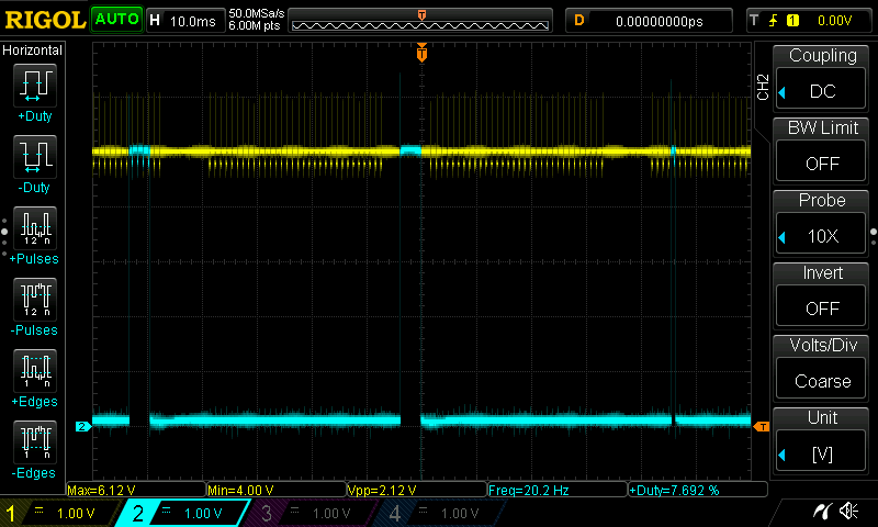
The internet search led me to a discussion on reddit that suggested to use a capacitor on the power supply line. Indeed, the data sheet for Sharp IR sensor also suggests the same thing. The data sheet for MaxBotix ultrasonic sensor also talks about the requirement for clean power supply:
Pin 6-+5V- Vcc – Operates on 2.5V - 5.5V. Recommended current capability of 3mA for 5V, and 2mA for 3V.
Pin 7-GND- Return for the DC power supply. GND (& Vcc) must be ripple and noise free for best operation.
Having only a 47uF polarized capacitor, I connected it to my junction strip between VCC and ground. The noise has subsided when compared to the previous result:
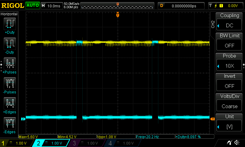
The output from the sensor is stable and back to normal:
1
2
3
4
5
data: 22
---
data: 22
---
data: 22
There is still some amount of noise that ideally I would like to minimize. I’ll try it when I get a bigger ceramic capacitor than the tiny ones I currently have.
