December 04, 2017 / by Sergey Kapustin
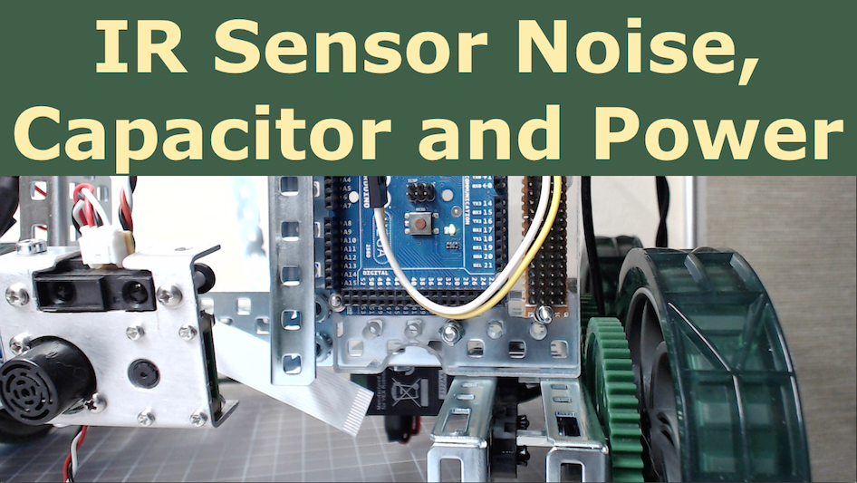
Ultrasonic Sensor Range Update
MaxSonar sensor can continuously update my Arduino program with the range values. Instead of writing serial, blocking polls to get the sensor’s data, I let the sensor push it to the Arduino.
The main benefit is to get notified about events in the environment as they occur. Otherwise, my program may be too late to react to an important condition. It also helps me develop software using event-driven model instead of procedural programming.
Roughly, the mechanism works likes this: MaxSonar outputs a pulse-width modulation signal (PWM) that alternates between high and low voltage level. When the level changes, the ATmega chip notifies my Arduino program via an external interrupt. Then, the program calculates a time span during which the voltage level is high. This duration can now be converted into a value that represents a distance between the sonar and an object in front of it.
To make it work:
- Connect the hardware
- Set up notification mechanism
- Write notification handler
On YouTube
Connect the hardware
First, I hook up the wires through a junction strip. The strip has common ground and 5-volt power coming from Arduino VCC. Since I plan to connect multiple sensors to that strip, I have to be careful not to exceed 200-milliamp limit on VCC.
Now, I need to designate a pin on Arduino that will receive PWM signal from the sensor. This pin should be able to support pin change interrupt, PCINT for short.
Note that there are two types of external interrupts: fancy interrupt (INT) and pin-change (PCINT) interrupt. There are fewer INTs than PCINTs due to their advanced functionality and more complex hardware. Since I plan to use other components that may require those advanced features, I choose to use PCINT to interface with the ultrasonic sensor.
The diagram at arduino.cc shows that analog pin 6 maps to PCINT14 on ATmega. As I find out later while testing the code, the selected pin would not work. While searching the internet, I stumbled upon a discussion about a similar issue.
It turns out that not all ATmega pins are mapped to Arduino, which includes PCINT14 (also named as PJ5). But notice how and where I went wrong. In the above diagram at arduino.cc, there are actually two PCINT14 defined: one at my originally selected location, which is PF6 another is at PJ5.
The datasheet for TQFP package of ATmega2560 does not show PCINT14 as a secondary function of pin PF6.
A bit more digging in pins_arduino.h for mega board, and I see this comment:
// A majority of the pins are NOT PCINTs, SO BE WARNED (i.e. you cannot use them as receive pins) // Only pins available for RECEIVE (TRANSMIT can be on any pin):
// (I’ve deliberately left out pin mapping to the Hardware USARTs - seems senseless to me)
// Pins: 10, 11, 12, 13, 50, 51, 52, 53, 62, 63, 64, 65, 66, 67, 68, 69 ```
So, is it a typo in the original diagram? Is this diagram of some older hardware revision? I’m sure someone has an answer.
Without investigating further, I decide to use PCINT16, which maps to analog pin 8 on Arduino.
Set up notification mechanism
OK, now I need to code the notification mechanism.
First, set up analog pin 8 for input:
1
2
3
4
5
#define PIN_US  A8

void setup() {
    pinMode(PIN_US, INPUT);
}
Next, enable interrupt on PCINT16:
1
2
3
4
5
6
7
8
9
10
11
12
13
14
15
void initInterrupts() {
    // Turn interrupts off
    cli();
    // Enable a pin group in control register
    PCICR |= (1 << PCIE2);
    // Enable individual interrupt on given pin(s)
    PCMSK2 |= (1 << PCINT16);
    // Turn interrupts on
    sei();
}

void setup() {
    ...
    initInterrupts();
}
Next, implement interrupt service routine. Here the code computes the time duration of the signal being high. In pulse-width modulation, it is a duty cycle:
1
2
3
4
5
6
7
8
9
10
11
12
13
14
volatile uint32_t us_cycle_tm_;
volatile uint32_t us_duty_tm_;

ISR(PCINT2_vect) {
    // This handler gets called whenever pin changes state

    int val = digitalRead(PIN_US);

    if (val == HIGH) {
        us_cycle_tm_ = micros();
    } else {
        us_duty_tm_ = micros() - us_cycle_tm_;
    }
}
Handle notifications
Now, I only need to convert the duty cycle to a range value and publish it to my ROS network:
1
2
3
4
5
6
7
8
9
10
11
12
13
14
15
16
17
18
19
20
21
22
23
24
25
#include <ros.h>
#include <std_msgs/UInt16.h>

std_msgs::UInt16 us_range_;
ros::Publisher sensors_("sensors", &us_range_);
ros::NodeHandle nh_;

uint16_t toCentimeters(uint32_t pulse) {
    uint16_t cm = ((pulse / 147) * 2.54);
    return cm;
}

void loop() {
    us_range_.data = toCentimeters(us_duty_tm_);
    sensors_.publish(&us_range_);
    nh_.spinOnce();
    delay(1000);
}

void setup() {
    pinMode(PIN_US, INPUT);
    initInterrupts();
    nh_.initNode();
    nh_.advertise(sensors_);
}
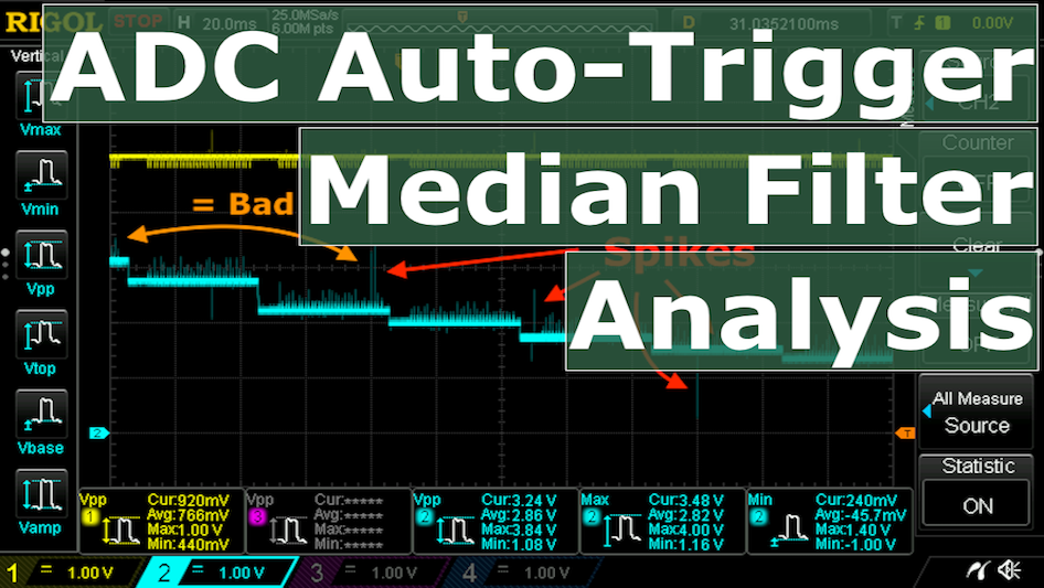
The code above publishes range value every second, but as seen from oscilloscope trace, ultrasonar signal changes twice in about 50 milliseconds. So, in one second Arduino receives 20 such notifications, which is PWM frequency. I can use this fact to filter out spurious readings from the sensor by calculating a median value and publishing that instead. I will also modify the code in the future to account for more sensors.
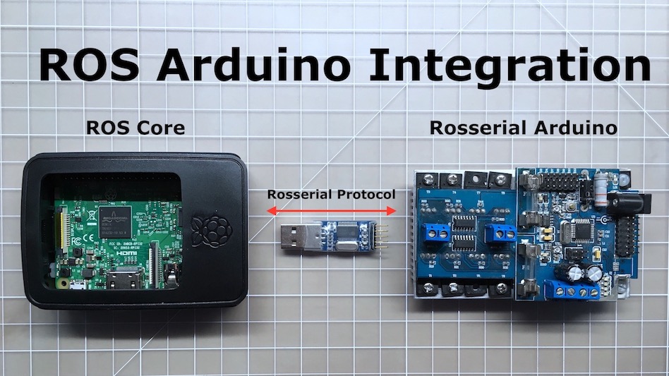
Once the code is compiled and uploaded to Arduino, I start three ROS nodes: roscore, rosserial relay, and sensor value subscriber. The following output shows range values from the sensor to an object in front of it in centimeter units:
1
2
3
4
5
6
7
8
9
10
11
12
13
14
15
16
17
18
19
20
21
22
$ rostopic echo sensors
data: 25
---
data: 25
---
data: 25
---
data: 25
---
data: 25
---
data: 25
---
data: 25
---
data: 66
---
data: 66
---
data: 68
---
data: 68
All in all, I’m happy with the result and ready to move on to my next task.